Friday, January 30, 2015

Cable Shifter

<<                                                             >>

Major System Category: Transmission
Task: Mount Cable Shifter
Parts: 991 Cable Shifter
Prerequisite Tasks:
Additional Costs: Part of the transaxle purchase
Time Requirement: 8+ hours
Date Started: January 26, 2015
Date Completed: January 30, 2015
The 991 transaxle is the 7 speed I purchased from GBox. It came with the cable shifter. The GTM is designed for the much older G50 transaxle and a cable shifter that is housed in a square metal box. If you go with a rebuilt G50, then you won't have much of a problem, because everything will fit.
Porsche 991 cable shifter and Vraptor shifter mount.
The G50 transaxle first went into a production 911 in 1987. I was much taller, thinner and younger in those days. Sometime between then and now, Porsche quit producing square cable shifter housings and switched to curved polymer housings. Guess what, those don't work very well with the GTM bracket welded to the frame where the cable shifter bolts on horizontally.
Vraptor  cable shifter mount. The smaller piece (top) bolts to the frame. The larger piece is designed to attach to the rear of the cable shifter and it bolts tot he smaller piece. 

The current list of changes caused by going with a non standard transaxle are as follows:
  1. Redesign, cut and weld the transaxle bracket to accommodate the wider 991.
  2. Build a cradle to hold the inverted 991, and deal with fitment of the drain plug.
  3. Order new half shafts for the CV joints.
  4. Order special bolts from Porsche to attach the 930 CV to the transaxle. You need 12 of these and Porsche charges $4.50 per bolt. Trust me, you can't find these bolts anywhere else.
  5. Purchase an extra set of cables and perform magic to connect them. Jim at cableshift.com was a big help!
  6. Fabricate a mounting bracket for the cable shifter. I purchased the Vraptor Speedworks cable shifter mount. This proved to be a good starting point.
  7. Finally, (I hope), a 7 speed shifter knob (in the correct pattern) and boot. I got this at Gaudin Porsche Parts in Las Vegas. Mark helped me with this purchase.
Porsche 991 cable shifter and top part of the Vraptor bracket. I'm just trying to get an idea of how this is all supposed to work.
The GTM design envisions bolting the cable shifter to the side bracket in the upper tunnel. The 991 cable shifter envisions four or five bolts into some kind of flat plate for a vertical mount. And did I mention, it is a round polymer shape.
I ended up enlarging the opening for the cable connectors. This was pretty easy using cut off wheel on the die grinder.
I figured out I use the Vraptor mounting bracket as a staring point. This is a two piece bracket that bolts a smaller piece to the frame and establishes an angle. The larger piece bolts to the cable shift box and then to the smaller piece. 
This is the bracket looking straight down. The cable shifter bolts into the rails. Ignore the four holes. They all had to be moved towards the passenger side (bottom) because I failed to account for the square piece inside the frame that is supposed to be used to bolt the G50 cable shifter to the frame. 
I had some angle aluminum stock. This may not sound very exotic, but I have discovered that you can fabricate a number of useful things for the car using this stuff. Since most of it will be hidden, it doesn't have to be a perfect job - just functional. I designed the bracket so I could bolt the cable shifter vertically into the angle stock. There are four 1/4 inch holes.
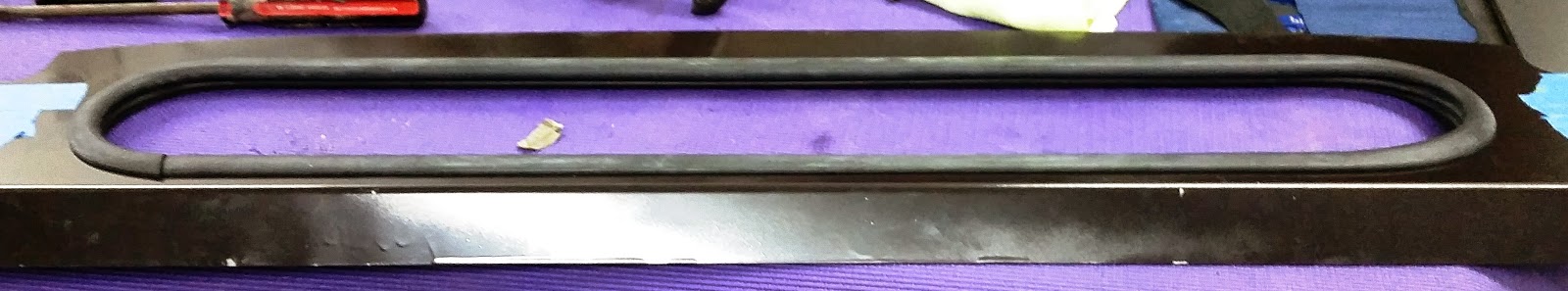
I trimmed these two parts off the cable shifter. They were just plastic.
The 991 cable shifter had an index tab and an additional hole. I had to cut these off the shifter, because they were not going to work for me. I used to get nervous about things like this, but now I just think it through and keep working.
Vraptor lower mount bolted into the frame.

I bolted the bottom piece of the Vraptor mount to the car, then clamped the larger piece to that one. This allowed me to work with the bracket and determine where metal needed to be trimmed so I could accommodate the frame.
I had to remove some material to accommodate the driver's side of the frame. After a fair amount of mumbling, wandering between the car and bench and maybe a harsh word or two. I had something that worked.
The front side of the bracket needed to be secured to the inside top rails of the tunnel. For this I used a heavy, straight aluminum bar. I bolted this to the front of the bracket, then cut 2 three inch pieces of angle stock so i could bolt one end to the bar stock and rivet the other end into the top frame of the tunnel.
Frot bracket. It is attached with rivets to the inside of the top tunnel frame.
I reinforced the area where I bolted the shifter to the bracket with 2 six inch steel strips. I wanted this piece to be as solid as the Wing mount on the back end of the car. I put everything together, then crawled into the car and got the masterpiece bolted in place.
Finished product sitting on the bench.

Finished product installed in the car.

Tuesday, January 13, 2015

Cockpit Rear Window Construct

<< Body Shell Prep                           >>

Major System Category: Body (Shell)
Task: Finalize rear cockpit window
Parts:
Prerequisite Tasks:
Additional Costs: Set Belt restraint bar  $200
Time Requirement: 2 hour
Date Started: November 1, 2014
Date Completed:  January 11, 2015
I needed a break from the wiring problems, so I started working on parts of the car that I could finish and put aside. The rear cockpit window is such a part. One design change I made was to go with a racing 4 point restraint system rather than the Corvette 3 point system salvaged from the donor vehicle. To make that work I needed a restraint bar.
The seatbelt restraint bar.
This is a hefty piece of gear with attachment points welded for easy bolt on to the chassis.
Painted black.
I purchased a restraint bar from one of the other GTM builders on the Factory Five Forum. The restraint bar bolts through the rear cockpit window frame and directly into the chassis. It is a great design. I started on this on my final 2014 trip down south to the new build site. The build manual calls for the application of a cloth covering. I decided to just paint the frame and the restraint bar black. I had a small paint booth already established and proceeded to the paint the parts
Rear cockpit frame. I would suggest mounting this in the car, before working with it so you understand the orientation.
Painted black.
On mt next trip down, I moved all the glass to the new build site. This included the cockpit rear glass. Some people have replaced this with clear Lexan, I decided to stick with the glass. The hardest part of the installing the gasket is in the half circles on either side of the frame. I started the gasket on the straight portion of the frame and worked my way around.
Gasket tool provided with the Factory Five kit. Use it. It makes the job easier.
Gasket installed.
Factory Five provides a gasket tool. It works to a point. The trick here is to get as much of the window into the gasket as possible. I tapped the edge of the cockpit frame on the floor to drive the window further into the gasket. This got it far enough into the gasket so it seats into the gasket. A friend suggested you could uses soap to ease it into place. The gasket tool comes in handy to pull the lip of the gasket over the edge of the window. 
Rear frame, window and restraint bar. Obviously, the blue tape is there for protection. It will be removed on final assembly.

Everything bolted together.

Friday, January 9, 2015

Racing Wing (optional component)

<< Weld Wing Mount to Transaxle Bracket                          >>

Major System Category: Brakes & Suspension
Task: Mount Racing WIng
Parts: Wing Mounts
             Racing Wing
Prerequisite Tasks:
Weld Wing Mount to Transaxle Bracket
Additional Costs:
Vraptor Speedworks Universal Wing Mount $489
APR GTC-300 Carbon Fiber Wing $1350
Time Requirement: 4 hours
Date Started: January 6, 2015
Date Completed:  January 8, 2015
I told my long time sparring buddy that I was getting ready to cut into the back end of the car. He expressed concern. I explained that after this much time on the car, very little frightens me anymore. Besides fiber glass can be fixed.
The wing arrives in a long box and wrapped in bubble wrap.

To give a sense of scale, the rolling bench is 48 inches long. The wing is 67 inches.
 All parts are purchased from Vraptor Speedworks (Shane does a great job). The Vraptor wing is the same one offered through the Factory Five website. The main difference is the attachment points are custom to the Vraptor mounting system. This is a very solid piece of gear. The back end is greatly reinforced by this addition.
The initial cut. I originally figured it would be 7 1/2 inches long. I needed 8 inches to make everything work.
I added rear body shell louvers to the build. I masked off the area, and came up with a rough measurement of 2 7/8 inches from the edge of rear louver opening. The mount comes in three parts that are bolted tot he welded transaxle bracket, then bolted side ways through slots for the portion that pokes through the rear body shell, and finally the third piece that rests above the body shell. All that to say I was inside of a 1/4 inch and well within tolerances for the mount adjustments.
The cut needs to be this wide to work. I already have a solution for cleaning up the edges.
I used a angle grinder to make the initial cuts. Once those were wide enough, I used a rigid sanding wheel on a die grinder to shape, smooth and widen the cut. I strongly recommend wearing a breathing mask and face shield. There is a great deal of dust released when cutting into the back end like this.
This is the middle part of the bracket poking through the hole. This is secured to the bottom bracket by three bolts.

The cut ended up being 8 inches long. I ended up about 1/2 inch off the rear of the car, and I had to trim some material around the exhaust vent openings. Keep the socket wrench and hammer handy, because I had to loosen the bottom of the bracket and tap it back and forth to line things up.
This shows the middle and top part of the mount bolted together and the length of the cut.
The second cut went much faster (probably, because I had some idea of what I was doing).This was on the passenger side, and this is where I need to move it over a tad. I don't think the difference will be noticeable.
Driver's side mount installed. Once I got to this point, I knew I'd get to the end of this task tonight.
Once I had the middle and bottom brackets bolted together, it gets very easy. The one thing I ran into was the bolt closest to the rear of the car is snug. Not uncomfortably snug, but I had to use hand tools and not my power tools to tighten it up.
Both mounts in place. I have a card board covering for the rear louver.
The rest is very straight forward. I was really excited to see the wing on the mounts on the car. Granted it is just resting on the mounts, but that's not a big deal.
Yes!

Search Engine Submission - AddMe