Showing posts with label supercar build. Show all posts

Saturday, November 28, 2015

Wing Window NACA Ducts (optional component)

<< Body Shell Prep                           >>

Major System Category: Body (Shell)
Task: Rough installation of NACA Wing Vents
Parts: NACA Wing Vents Carbon Fiber
Prerequisite Tasks: Install the rear cockpit window
Additional Costs: $1500
Time Requirement: 4 hour
Date Started: November 1, 2014
Date Completed:  January 11, 2015
This is one of those tasks that is dependent on the bank account. However, in late June the time arrived when I had enough money scraped together and put in my order for the NACA Wing Vents. These are available in either fiber glass (boring) or carbon fiber (yes!) These vents replace the rear quarter windows. Unless you have an extraordinarily flexible neck, you were never going to be able to see out of these windows anyway.
Carbon fiber Naca vent.
These provide  functional cold air intake. The intake off the manifold is a double "U" shaped duct that runs the length of the engine and can be position directly next to these entry ducts.
The NACA vent overlays this window. This does add an extra step, because now you have to account for the interior.
I chose carbon fiber to match the carbon fiber wing and to tie the carbon fiber to the interior accents. To get these fitted to the body shell is basic grunt work. The tools I used were a reciprocating saw, a die grinder and a cutting wheel.
This is a rough measurement of the cut. Becareful, otherwise, you'll have to do some repair work.

The cut needs to be tear drop shaped, because the shape of the duct dropping into the vehicle behind the rear fire wall . 
You can see how the underside of the vent slopes at an angle. This is why you need to make a tear drop shape cut.

Note: There are a number of things that you need to consider:

  1. The location of the rear fire wall. Obviously the duct cannot extend into the roll bar. Provided everything is mounted properly between the body shell and chassis, this should be okay. But you will be cutting opening very close to this margin.
  2. The fuel cap opening may touch the bottom of the NACA duct piece. I anticipate I will have to make an accommodation for this when I get there.
  3. This is a recent photo where I was working on door fitment. I had to remove material from the rear pillar to get this right. The gaps in this photo are not finalized.
  4. The duct piece has a lip that anchors against the rear door jamb. This will require additional sanding to remove material so the door can close.
This is the passenger side duct. You can see where there is some interference with the fuel cap.

Sunday, August 23, 2015

Cockpit Rear Window Install

<<  Cockpit Rear Window             Overhead Console  >>

Major System Category: Interior
Task: Install rear window
Parts: Cockpit Rear Window and helpers
Prerequisite Tasks: Cockpit Rear Window
Additional Costs: N/A
Time Requirement: 30 minutes
Date Started:  April 25, 2015
Date Completed:  April 25, 2015
This is a very quick task with one slight catch. You need three hands. I know some of you are saying, "Well you're a ninja something or other, use your foot." Even Ninjas run into problems from time to time. Of course, I have resources very few builders can claim - grand kids! In this case, Ethan and Zachary. So now I have six hands and and people short enough to easily fit inside the cockpit.
The problem is to install the window here. As you can see there is a lot going on here, and not much room. This is taken from the rear of the car through the engine bay to the front.
Installing the rear window is really a very big step in working out the rest of the interior. I found I needed to know exactly where this fit inside the car and I have done numerous measurements from the back window as I worked on the overhead console and NACA wing vents.
Everyone piled into the car. I had the doors on the car to make sure no one fell out.
Because the window is installed in the window frame, there is no easy way to reach a hand around the car and hold the nut and bolt for the frame, plus hold the frame up. My solution was to recruit helpers (this did involve a trip to Sonic and some ice cream).
Zachary on the driver's side as the lift goes up.

There goes Ethan on the passenger side.

With helpers, the rear cockpit window was easily installed and secured in less than 30 minutes. I raised the car on the lift and clambered up a ladder into the engine bay. The kids had a blast.
Rear window taken from the driver's side. You can see some wires coming through the top of the frame. These have to be threaded at the time of installation.

Same view from the passenger side. The wires come from the second power cell installed in the engine bay.

Saturday, February 14, 2015

Mount Half Shafts

<< Axle and CV Joints                                         Diffuser  >>

Major System Category: Transmission
Task: Install half shafts between rear hubs and transaxle
Parts:
New Half Shafts (Custom Made)
Prerequisite Tasks:
Additional Costs: $1300
Time Requirement: 8+ hours
Date Started: November 15, 2014
Date Completed: February 14, 2015

The governing principles for Super Car Build are quite simple:
  • Failure is not an Option - Unknown
  • Never, never, never give up. - Winston Churchill
I decided that to do this job right it might take longer than I wished, and probably cost more than I anticipated. Okay. I refuse to end up as one of those guys with a half built car and a $50,000 price tag for failure.
This is an assembled half shaft per the Factory Five Manual. Looks good and it certainly would fit a G50 transaxle. But I have been off the reservation  since I went with the 991 transaxle. 
The half shafts should be a simple task. Some grunting, scraped knuckles, a few choice words, but nothing that should take months to complete. In my post on the Cable Shifter, I listed all the things up to that point that had to be adjusted for going with a Porsche 991 transaxle versus a Porsche G50. It is a long expensive list, but the end result is a state of the art, 7 speed transaxle straight from Germany. The kind of transaxle a super car deserves.
The green circles show the shaft stubs on the 991 transaxle. They measure out around 22 inches. I know you're supposed to get this stuff down to the 1/4 inch. However, there is enough play that you have some room to work with.
I assembled the half shafts with the Corvette CV joint on one end and the 930 CV on the other end. It took a little time, but it was a straight forward task. The next day, I planned to install them. I slid the Corvette CV into the Corvette hub and tried to get the other end of half shaft to connect to the transaxle. Guess what, when the shaft is several inches too long, it just isn't going to happen. The problem arises that the width of the G50 between the shaft stubs is 10 inches. The width of the 991 is 22 inches. At the time, I didn't know what the width of G50 was. I know now it is 10 inches.
This is the half axle from the Drive Shaft Shop. No, it isn't made out of gold. My buddy Brian commented that it was a beautiful unit. It is - these guys do good work.
I sent an email to Factory Five support and asked them for that dimension. They didn't know the answer. Then I asked them for assistance in specing out new half shafts. They buy their shafts overseas and couldn't help either. What about the spline count. They thought it was 28. Ever count splines by hand - you might go cross-eyed. The only thing they said was figure out the difference and divide by 2. Duh, I ALREADY KNEW THAT!
I ended up taking off the caliper, rotors, tie rod and shock absorber to get a enough room to work. My buddy Charlie chided me that I was supposed to be putting things together. In this photo, I was doing the heat - tap - heat  -tap process to get the CV splines through the hub.
If Shane (Vraptor SpeedWorks) had had a G50 sitting on the floor of his shop, he would have measured it for me. I ended up getting the dimensions from GBox. Trust me, wherever they have the dimensions posted on the web is well hidden. There are diagrams, but they are so distorted that you can't read any numbers off of them.
This bolt is the correct size and that is the Torx head I needed to install it.
I don't know what caused me to check, but I decided to see if the bolts fit. Of course not. Porsche in their modern transaxles have switched to a M10 x 1.0 mm thread. These are about as common as the proverbial unicorn at the end of the rainbow. I tried finding these on my own, and finally called Carousel Porsche Audi in Golden Valley, MN (where I had the Boxster serviced). They ordered me 12 bolts designed for the 991 transaxle. And I thought I was home free, I was just getting in line for another smack across the head.
My weapon of choice (eh, I mean tool) to get this monster assembled.
The assembled half shaft with CV joints on both ends is smidgen over 30 inches long. The actual shaft if 23 inches long. This means I needed a half shaft that was 17 inches long before I added the CV joints. I probably double checked this measurement 100 times. I knew this was not going to be cheap. I ended up ordering custom half shafts from the Drive Shaft Shop. It is a good thing they knew their business, because I certainly was swimming in the deep water. He told me how much it was going to cost. I swallowed hard and gave him my VISA info. They were on the door step in two days. These guys do really good work.
This is a beautiful sight. Normally, it takes about 20 minutes to get here. I had a minor 4 month detour.
So now I have the bolts and the half shafts. Everything should work - right? The first problem I run into is that the splines on the Corvette CV joint are new (versus the ones I got from Fparts on the donor pallet - that seems like a million years ago). The spline is correct, but these buggers are really, really tight. There is a new hardware store 3 miles down the road from the NSMC. The dog and I ended making two trips that day. The first one was to buy a torch.
Installed! I was on top of the world, and greatly relieved that it finally worked.
I used the torch to heat up the hub and heat up the end of the Corvette CV that goes through the hub. It took about 15 - 20 minutes on each side to heat, tap lightly with a hammer, heat - tap -heat - tap. The Corvette CV joints that came with the donor pallet use a 34mm nut. I had purchased a 34 mm socket. The nut required for the new CV uses a 36 mm socket. No, I didn't have one of those behemoths handy. This precipitated trip #2 to the hardware store. The pup was beginning to think I was insane.
Bracket installed on the chassis to reinforce the area that I had to remove material from.
Back at the NSMC, I believe I see light at the end of the tunnel, or it could be an in bound train. It was a train. I get lift to the proper height, I position CV and I can't get there from here. The problem  is the cradle I built for the transaxle to keep the drain plug safe. I did this, because I didn't want to cut into the chassis. <Sigh>. The only way to make this work is to cut into the chassis. Out comes the cutting wheel and angle die grinder.
Another look at the channel brace I built.
A long time ago, my dad was faced with a similar problem. A building inspector decided that two 7 inch logs was not sufficient to support a structural truss. This was a bunch of hooey, but dad was also driven to get this house built. A few days later he showed up with channel braces that distributed the load else where. I adopted this idea, and created a sleeve to reinforce the area where I cut away material. My dad was a brilliant engineer. I'm just a kid using his idea. I built the sleeve and removed the cradle. Now the everything should fit - right? Nope.

Those bolts that I special ordered from Porsche -  they were short. However, I had one thing that I never had when I looked for those bolts on my own - a Porsche part number. I maintain an office at the NSMC. So I sat down and brought up Pelican Parts. I found the bolts for the 991 transaxle (M10 x 1.0 x 46mm). I also saw in the related listing transaxle bolts for 997 transaxles. A different part number. I clicked on that link and discovered that Porsche changed the bolts when they went to the 991 transaxle. The older bolts are M10 x 1.0 x 50mm. Well what did I have to lose, I ordered 12 bolts. (I have  acquired several sets of bolts that do not work in this application.) I was already a gazillion bucks over budget on this task, what's another $20. My dad was driven to build a house; I'm driven to build a car.

The new bolts arrived. I tested them in the transaxle and they were the correct thread and pitch. They were long enough going through 930 CV. I hooked up the air ratchet and attached the biggest Torx bit I have. Literally, 20 minutes later I had everything attached!

"Never, never, never give up!"

Saturday, September 20, 2014

New Southern Man Cave

One of the outcomes of the build is the New Southern Man Cave (NSMC). One of the really big problems with living in a northern state is winter. It cuts down on driving days and building days. Even with a propane based bullet heater, there are three to four months out of the year where it is too cold in the garage to get much done.

The second problem (not for the build, but afterwards) is that running three or four cars in two car garage is not a long term solution. Granted, I have a storage space for one car (usually the Boxster) in northern Minnesota. I have been truly blessed to have that space. The prospect of parking either the Boxster or the GTM outside just doesn't work for me.

My wife and I decided (basically, I got permission, but decided sounds so much better) to build the New Southern Man Cave in South Carolina. There are about 10 to 15 days per year where the weather is truly horrible. I can congregate all the cars in one place, and we get the lift out of the Northern Man Cave - something the love of my life will truly appreciate. She's been a really good sport about having a lift shoehorned into the garage, but all things come to an end.

The New Southern Man Cave is located on a former bean field about 20 miles inland from the Grand Strand. It is 75 x 30 feet (2250 square feet) with a clearance of just under 11 feet. It has sufficient space to park the Boxster, Corvette and GTM, a paint booth that can be taken up and down, tool chest and work bench, the lift, electric hoist, small welder and air compressor. Plus, it could hold additional project car (or two - I wrote the last bit really quietly).

*     *     *
When I started this post, the NSMC was in the planning stages. Somewhere in between planning, building and moving the build from Minnesota to South Carolina life stepped in. My mother suffered a fall in April 2014, and a good chunk of the summer went to dealing with the crisis. She is much better now. Needless to say, between family issues and running a business, the GTM build took a back seat.

The NSMC was completed in May. I only had a week to set up things in May, before heading back to Minnesota. By the end of summer, the GTM and Boxster joined the Corvette; the lift was reassembled, an overhead hoist for the engine and body was installed; a ground winch was bolted into the slab; and Internet service was established. The move was not trivial, but I worked with a number of great vendors:

  • Benco - The original vendor that I purchased my four post Direct Lift from in 2011. They came and dismantled the lift, then shipped it to South Carolina.
  • Quality Air Tool -  I was very fortunate to find the nearest Direct Lift vendor to the NSMC was in Florence, SC, which is 50 miles up the road from the NSMC.
  • Select 1 -  These folks transported the cars to the NSMC. They showed up on time, demonstrated great care  car for the vehicles they were moving and delivered them on time. They were recommended to me by my wife's cousin.
  • Homewood Metal - These folks built the NSMC. Mr. Jimmy is a gentleman, true to his word and schedule. The NSMC is absolutely fantastic!
This required planning, timing and money. So nothing major happened on the build this summer. The neighbors near the Northern Man Cave are disappointed with the move. They wanted to see the car run, but in reality it would have been very difficult to do all the required body and engine work on one side of a double garage that already has a lift and a car. The rest is a pictorial of the NSMC and the move.

This is mid April, 2014. The steel frame is going up.

Early interior shot, early May 2014. The building is fully insulated.

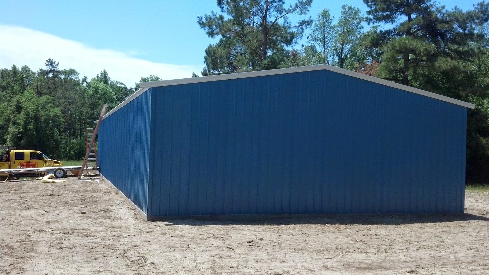
Early exterior shot, early May 2014.


Moving Day. This was late July 2014.

She had to be winched into the truck.

Settled in for the long ride.
Early August 2014 - Arrival day in South Carolina. The drivers for Select 1 are fantastic.

This car that has smudged primer, no engine and no glass attracted a HUGE amount of attention. This was the first time it had ever been out of a garage and I was able to take photos from a number of angles.

No one really knows what a Factory Five GTM is. So I explain it is based on a C5 Corvette, with the engine the rear hooked up to a 7 speed Porsche transaxle with some Ferrari like styling. Then they ask, how fast can it go. I explain that the estimated top end speed is 207 mph. I'll never take it that fast, but that's what my calculations estimate.

Did I mention friends? This is Charlie, my neighbor from Richmond, VA. He helped me get the GTM into the NSMC. He was so happy to find out the towing package on his SUV really works.

My son in law made the Corvette photos for my birthday.
This is the Swisstrax floor from the Northern Man Cave. I picked it up, put  it in the Van and reassembled it.


All the cars in one place and plenty of space. You can see the rolling bench next to the GTM. I was very busy getting things put together.

Just before Labor Day, the lift arrives!
The lift is back in business.

Of course, it wouldn't be complete without the Lift Lytes. One of the best accessories for any lift.

Overhead hoist (Northern Tool and Equipment) for the engine and body work. Essentially, I can do everything as a one man shop.

We all have to answer to someone. I answer to 9 lbs of Attitude.

The lift went to use immediately. The Corvette goes up for some much need maintenance.
There was never any room in the Northern Man cave for a rolling bench. Now there is plenty of room.

Long shot of all the cars.

My grandson, Zachary, came to help me get the GTM covered. He is really into cars.

Sunday, November 10, 2013

Hazard Wiring - Circuit 4/6

<<  Windshield Wiper Harness - Circuit 3/5          Parking Lights - Circuit 4/8 >>
                                                                             Weather Pack Connectors
Major System Category: ISIS
Task: Hazard lights
Parts:
Prerequisite Tasks:
Additional Costs:
Time Requirement: 3 hours
Date Started: November 7, 2013
Date Completed:  November 7, 2013
The hazard lights are one of those circuits that runs the length of the car. This circuit was assigned to Power Cell #4, which did not get installed until Fall 2013. However, the planning and preliminary wiring for this circuit took place in Fall 2012. I had to think about how this was going to work out 14 months prior to getting this done.
Hazard circuit terminal block. This located on the center aluminum panel in the front bay. This photo was taken prior to mounting Power Cell #4.
I decided that once I had the hood installed and centered, it was never coming off the car again. I made this decision for a couple of reasons:

  1. There are too many systems tied into the hood (e.g. head lights, fog lights, signals, sensors, grille).
  2. The hood is not symmetrical. Prior to mounting the hood, I spent three days with the cross hatch laser level figuring out that it was off center. Once I had it mounted on the car, I decided I was not taking it off again.
The yellow wire in the lower left is the hazard circuit coming out of the left front turn signal and going through the conduit along the hood above the grille.
The hazard lights are located on the four corners of the car. Regardless of the power cell location, I was going to end up running wires a long way. I have gotten better at the concept that even though car is approximately 16 feet long, a wire run like this is probably closer to 20 feet due to path down into the tunnel and back up around the engine bay.
This is the other side of the hazard circuit coming out on the right front of the car. The yellow wires run to the other signal then through the conduit to the terminal block.
I mounted a terminal block where one side is daisy chained (i.e. all sockets are wired together on one side). This means a single power lead distributes power to all ports on the terminal block. Based on my design, I knew where Power Cell #4 was going to be mounted, so prior to purchase I built the hazard circuit terminal block next to the power cell location and wired the circuit into the front signals. I also ran wires to the rear of the car for the rear signal lights. This conduit comes out at the rear of the tunnel close to the cable box for the manual parking brakes. The rear power leads are split to go around the engine bay and up to the rear lights.
The yellow wires are the rear leads from the terminal block. They run under the Vintage Air unit through a large conduit to the rear end of the tunnel. The braided cable is the cross over pipe for the fuel tanks.
By law (as I understand it), the car is required to have a physical hazard switch. The switch is slated to be mounted on the center console below the touch screen and forward the gear shift. Since I am using ISIS, I just need to run the signal wire and a ground to this switch to complete circuit.
The hazard circuit (yellow wires) split to the left and right into conduits that work around the engine bay to the rear lights. The rectangular item in the lower left background is the cable box for the manual brakes. These run under the engine.
These are circuits enclosed in wire loom that run around the engine bay and next tot he splash guards.

Search Engine Submission - AddMe