Sunday, November 23, 2014

Axles and CV joints

<< Transaxle Install                        Mount Half Shafts  >>

Major System Category: Brakes & Suspension
Task: Assemble Half Shafts
Parts: Inner and Outer CV Boots
            Corvette CV Joints
            Porsche 930 CV Joints
            Porsche 930 CV flange
            Axle Grease
            Axle Half Shafts
Prerequisite Tasks:
Additional Costs:
Porsche 930 CV Joints $140
Porsche 930 CV flange $34
Lucas Oil Heavy Duty Grease (2 lbs) $14
Time Requirement: 3 hours
Date Started: November 22, 2014
Date Completed:  November 22, 2014
This task really doesn't have a prerequisite in the conventional manner. You can build these at any time. My approach was to wait for the transaxle to be mounted in the chassis. At this point, I am just waiting on getting the correct bolts to connect the 930 CV joints to the 991 Transaxle. This isn't a very difficult task, it is just messy. 
I used this end for the outer CV. This is the Corvette CV joint either from a parts pallet or donor car.

I used this end for the inner CV joint. You can see the groove for the retaining ring is closer to the edge.

The inner and outer CV boots come with grease and retaining rings. I don't think there is enough grease included, so I purchased the additional grease. The first thing you notice is that the ends of the half axle shaft are different and the manual is a bit vague as to which end is for the Corvette CV joint and the Porsche CV joint. I don't think it really matters. I have a digital copy of the manual, so I blew up the photo on the page and determined the end assembled for the inner CV boot.
This is the 930 flange and the inner cv boot. You will not get confused here. The inner boot is significantly smaller than the outer boot. 

The other difference betweent he inner and outer boots, is the inner boot fits inside the 930 flange, where the outer boot fits over the Corvette CV joint.

The other thing I found was that the inner boot is really tight when pushed onto the shaft. The outer boot is a bit loose. Before installing the inner boot, pop it into the 930 CV flange. It should be an easy fit. The flange will hold the lip of the inner boot against the 930 CV joint.
930 CV joint and inner boot attached to 930 Flange. 

The flange sits on the 930 CV joint. Granted installation to the transaxle will be a bit more challenging, because things will be horizontal and the whole is going to want to fall through the chassis and hit the floor. Just one of many joys in working on this car. I haven't decided whether I want to lean over the top  or raise the car tackle that install from the bottom.
Now for the messy part. The 930 CV joint is new, so it needs to be packed with grease. You want to make sure you avoid filling the center, because the axle needs to fit through there and it is just cleaner. Disposable plastic gloves are highly recommended. I also used a spreader to scoop and move the grease around. It is the same kind of spreader I have used on the fiber glass.
Porsche 930 CV joints packed with grease.

The Corvette CV joint repacked with grease. You can see the spreader to the left; I also clamped this in a vice to make it easier to work with. You just want to make this snug, because splines that attach to the C5 hubs is what I used to hold this steady.
Since I am still figuring out the CV bolt size for the 991 transaxle, I packed the 930 CV joints and sandwiched them between some cardboard. I thought the correct size for the bolts was M* x 1.25 x 50mm, because that's what Porsche used on the 997 transaxle. WRONG! My current theory is that I need M10 x 1.25 x 50mm. Once I fgure that part out, then I have to round up 12 of them.
Outer boot slips over the outside of the Corvette CV joint. Then you put a retaining ring on the boot.

One side finished, just repeat on the other side.

Saturday, September 20, 2014

New Southern Man Cave

One of the outcomes of the build is the New Southern Man Cave (NSMC). One of the really big problems with living in a northern state is winter. It cuts down on driving days and building days. Even with a propane based bullet heater, there are three to four months out of the year where it is too cold in the garage to get much done.

The second problem (not for the build, but afterwards) is that running three or four cars in two car garage is not a long term solution. Granted, I have a storage space for one car (usually the Boxster) in northern Minnesota. I have been truly blessed to have that space. The prospect of parking either the Boxster or the GTM outside just doesn't work for me.

My wife and I decided (basically, I got permission, but decided sounds so much better) to build the New Southern Man Cave in South Carolina. There are about 10 to 15 days per year where the weather is truly horrible. I can congregate all the cars in one place, and we get the lift out of the Northern Man Cave - something the love of my life will truly appreciate. She's been a really good sport about having a lift shoehorned into the garage, but all things come to an end.

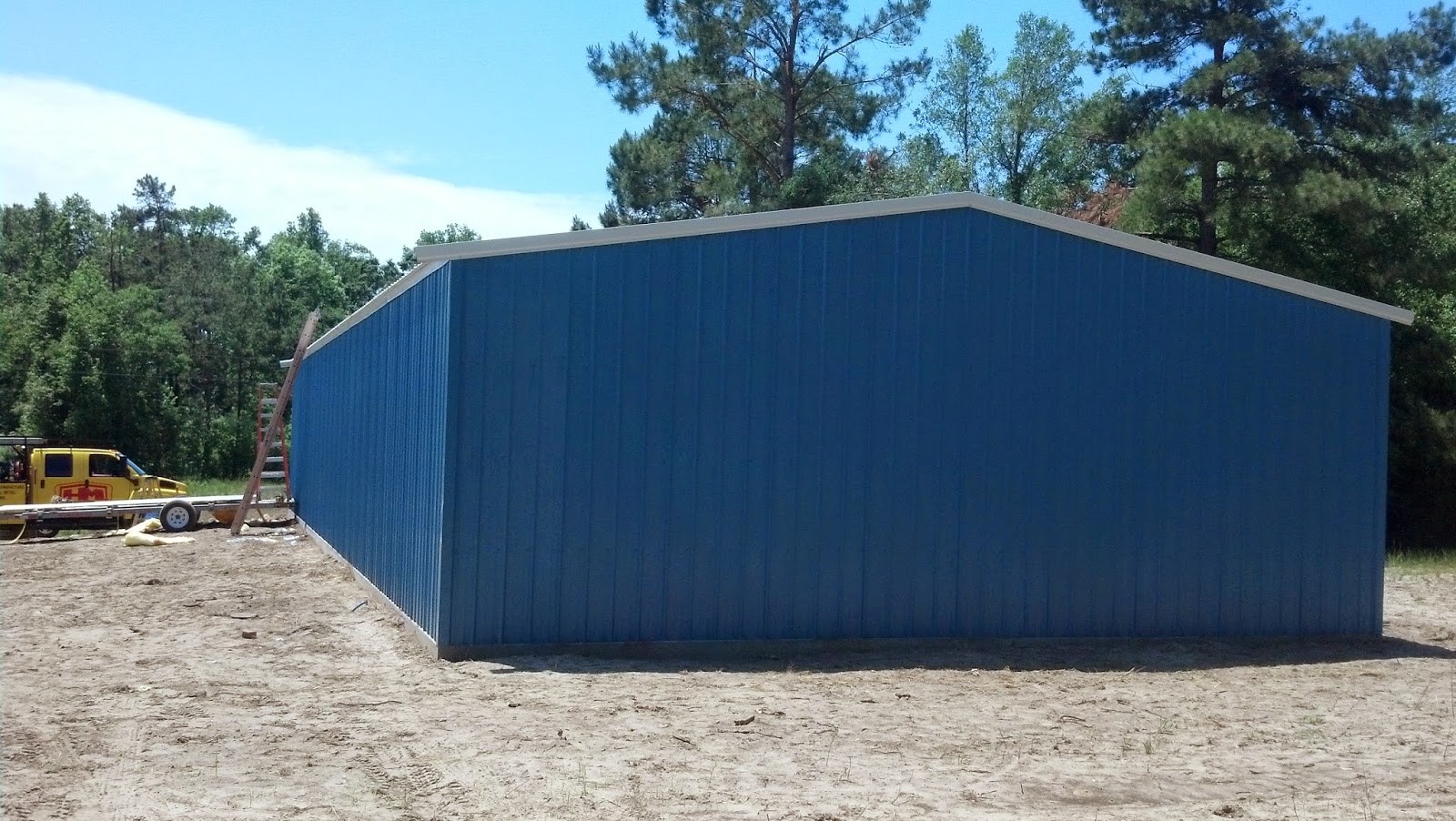
The New Southern Man Cave is located on a former bean field about 20 miles inland from the Grand Strand. It is 75 x 30 feet (2250 square feet) with a clearance of just under 11 feet. It has sufficient space to park the Boxster, Corvette and GTM, a paint booth that can be taken up and down, tool chest and work bench, the lift, electric hoist, small welder and air compressor. Plus, it could hold additional project car (or two - I wrote the last bit really quietly).

*     *     *
When I started this post, the NSMC was in the planning stages. Somewhere in between planning, building and moving the build from Minnesota to South Carolina life stepped in. My mother suffered a fall in April 2014, and a good chunk of the summer went to dealing with the crisis. She is much better now. Needless to say, between family issues and running a business, the GTM build took a back seat.

The NSMC was completed in May. I only had a week to set up things in May, before heading back to Minnesota. By the end of summer, the GTM and Boxster joined the Corvette; the lift was reassembled, an overhead hoist for the engine and body was installed; a ground winch was bolted into the slab; and Internet service was established. The move was not trivial, but I worked with a number of great vendors:

  • Benco - The original vendor that I purchased my four post Direct Lift from in 2011. They came and dismantled the lift, then shipped it to South Carolina.
  • Quality Air Tool -  I was very fortunate to find the nearest Direct Lift vendor to the NSMC was in Florence, SC, which is 50 miles up the road from the NSMC.
  • Select 1 -  These folks transported the cars to the NSMC. They showed up on time, demonstrated great care  car for the vehicles they were moving and delivered them on time. They were recommended to me by my wife's cousin.
  • Homewood Metal - These folks built the NSMC. Mr. Jimmy is a gentleman, true to his word and schedule. The NSMC is absolutely fantastic!
This required planning, timing and money. So nothing major happened on the build this summer. The neighbors near the Northern Man Cave are disappointed with the move. They wanted to see the car run, but in reality it would have been very difficult to do all the required body and engine work on one side of a double garage that already has a lift and a car. The rest is a pictorial of the NSMC and the move.

This is mid April, 2014. The steel frame is going up.

Early interior shot, early May 2014. The building is fully insulated.

Early exterior shot, early May 2014.


Moving Day. This was late July 2014.

She had to be winched into the truck.

Settled in for the long ride.
Early August 2014 - Arrival day in South Carolina. The drivers for Select 1 are fantastic.

This car that has smudged primer, no engine and no glass attracted a HUGE amount of attention. This was the first time it had ever been out of a garage and I was able to take photos from a number of angles.

No one really knows what a Factory Five GTM is. So I explain it is based on a C5 Corvette, with the engine the rear hooked up to a 7 speed Porsche transaxle with some Ferrari like styling. Then they ask, how fast can it go. I explain that the estimated top end speed is 207 mph. I'll never take it that fast, but that's what my calculations estimate.

Did I mention friends? This is Charlie, my neighbor from Richmond, VA. He helped me get the GTM into the NSMC. He was so happy to find out the towing package on his SUV really works.

My son in law made the Corvette photos for my birthday.
This is the Swisstrax floor from the Northern Man Cave. I picked it up, put  it in the Van and reassembled it.


All the cars in one place and plenty of space. You can see the rolling bench next to the GTM. I was very busy getting things put together.

Just before Labor Day, the lift arrives!
The lift is back in business.

Of course, it wouldn't be complete without the Lift Lytes. One of the best accessories for any lift.

Overhead hoist (Northern Tool and Equipment) for the engine and body work. Essentially, I can do everything as a one man shop.

We all have to answer to someone. I answer to 9 lbs of Attitude.

The lift went to use immediately. The Corvette goes up for some much need maintenance.
There was never any room in the Northern Man cave for a rolling bench. Now there is plenty of room.

Long shot of all the cars.

My grandson, Zachary, came to help me get the GTM covered. He is really into cars.

Thursday, March 13, 2014

Lighting - Circuit 4/10

<< Mount DRLs                                                      Weather Pack Connectors >>

Major System Category: ISIS Wiring
Task:
Parts: Door Jamb Switchs
           Interior LED lighting
Power Cell: 4
Circuit: 10 - TAN
Master cell: PINK GREEN
Prerequisite Tasks: Mount DRLs
Additional Costs: Switches - $25
                              Interior Lights - $50
Time Requirement: 90 minutes
Date Started: August 10, 2013
Date Completed: August 10, 2013
The interior lighting is LED based. This follows the decision to go with LED lights everywhere possible. I believe the only non-LED lights are the head lights. These are HID bulbs. To me this is a proven technology as I have applied it to the Corvette and the Porsche.
This the hole for the switch.  This is drilled through the fiber glass and sheet metal.
  Of course, this is a GTM so there are still other things that have to be built to make interior lights work. I purchased the door jamb switches from Quick Racing Products. There are a lot of great products on this site. The switch is installed in the door. This is just the signal circuitry to the master cell. The power lead comes from Master Cell #4/Circuit 10 and this routed through a hole cut in the front fire wall.
The QRP door jamb switch installed.
The first thing that needs to be figured out is where the switch can be installed on the door. I determined that there is an average of 3.25 inches from the axis of the hinges on the frame to the edge of the interior body shell fiberglass. There is a 1 to 1.25 inch gap between the frame hinge and the start of the body shell fiberglass. This leaves about a 2 inch strip where the switch needs to make contact. I took door and measured 2.5 inches from the hinge on the door (this will vary from car to car) and checked to make sure there was fiber glass and not the steel hinge plate behind it. This is where I drilled an 11/16 inch hole for the switch.
Terminal block with signal wire from the master cell to the circuit.
I piggy backed the ground and signal wires through the same wire loom used for the door poppers and windows. These connectors are all wired through Weather Pack terminals.. I plan to have to use large diameter wire loom as an over all shield in the gap between the door and the car. The signal wire runs through the internal conduit above the tunnel and interfaces to the other signal wire (from the passenger side) and the signal wire to the master cell via a three position terminal block.
Under dash LED pod.
LED lights are three pods installed above the passenger and driver side foot wells. It is very busy under the dash. I used a strip in the Corvette to replace the bulbs. However, I didn't feel a strip would work in the GTM environment.

Monday, March 10, 2014

Weather Pack Connectors

<< Brake Lights - Circuit 2/3                                                                Next >>
      Hazard Wiring - Circuit 4/6
      Parking Lights - Circuit 4/8
      Lighting - Circuit 4/10
   
Major System Category: ISIS Wiring
Task: Build weather pack connectors for doors and tail lights
Parts: 4 x 6 way cinnectors
           2 x 3 way connectors
Prerequisite Tasks:
Additional Costs: $49
Time Requirement: 2 hours
Date Started: January 25, 2014
Date Completed: January 28, 2014
One of the things I worked on in late November was connecting the tail light and door assemblies into the main wiring circuits. I was so intent on just getting something to connect that I failed to consider the greater problem of moisture on these contacts. I recognized, correctly, the doors and tail light assembly need to be able to disconnect from the main chassis. I did not wire this up the first time through with any consideration to rain or car washes or any of the other things that can mess up an electrical connection.


These are the little parts that can get dropped, wander away or get lost. On left hand side of the dish are the posts. These fit inside the barrel terminals. The green insulator fits over the barrel connector and the reddish/brown are the individual wire plugs.
The other issue was that by making an individual connection for each circuit, I had a real mess of wires on my hands in the tail light area, and burgeoning mess in the door area. I understand today how everything connects, but what about three or four years from now when something quits working and I need to go into the area.
This is a 6 way connector for the passenger door. Two wires for the popper, the interior lights and power  windows. These wire colors correspond to the wire colors used for the circuits and those colors are dictated by ISIS wire circuit color.
My solution is to go with a weather pack connector that is water proof and vibration proof when it comes to connections. By the time I figured this out, winter had descended with a heavy hand on the Northern Man Cave. I only really got to work the first ten days in December, after that it was just too cold. I mapped out the wiring for taillights and doors. I had 8 wires running to the tail lights and six wires running tot he doors (not counting the speaker wires that I am going to run continuous from the head unit). This will be a maintenance problem.
These each go on the single bulb rear tail light.
The weather pack connector consists of two hard plastic pieces. One holds the barrels and the other the posts. There is a inner rubber insulator to keep water out that fits over the barrel connector and individual rubber plugs that slip over each wire. These are pressed into the back end of each connector. Wires are crimped to the post and barrel terminals. (I really suggest doing these one at a time so as not to get confused.)
These are not a bunch of dying cockroaches. These are the six weather pack terminals I built. Four for the tail lights and two for the doors.
I decided to go with a uniform six inch wire to form the pig tails. To this I measured out 1 foot and cut it in two. The rest just involves stripping the end of the wire and crimping it to the connector. These connects have two "ears" that hold the connector in place. The connector snaps into place. It can be removed using a special tool that fits over the connector and pushes the ears down.

Rear Stereo Speakers

<< Kenwood DNN990HD                                                   Next >>

Major System Category: Electronics
Task: Build speaker box for rear speakers
Parts: Wood Board
            Carbon Fiber Vinyl
            Infinity Reference 3032cf 3.5-Inch
Prerequisite Tasks:
Additional Costs: $75
Time Requirement: 6 hours
Date Started: January 14, 2014
Date Completed: January 21, 2014
Initially I was going to just go with speakers in the doors. There really isn't a good place to mount rear speakers. I started to look at the rear quarter glass. These are really worthless in terms of seeing anything. I plan to rely on mirrors and cameras to see what's going on around the car. Vraptor Speedworks sells a NACA duct that provides air into the engine compartment. I plan to replace the quarter glass with these ducts and use the ducts to push air directly into the cold air intake.

Everything seems so straight forward when you start out. I am just fitting the box together using clamps.
This solves two problems as it now gives me a place to mount the rear speakers. 
The tricky part was getting the hole centered and big enough. I came across a great multiple hole saw kit for about $12 that handled everything from 1/2 to 6 inch holes. 
There are no mounts for rear speakers in the GTM design. There are only mounts for door speakers built into the inner door liners. I 6.5 inch speakers for the doors and 3.5 inch speakers for the rear. Time to make rear speaker mounts!
This is sanded on the seams, glued and screwed together. The speaker wires are running through the small hole in the back of the box. I also have a rubber grommet installed to minimize chaffing. 
I found a sturdy 1 x 12 x 48 pressed board at Home Depot. This is your basic 7th grade shop project where you need to build a box. I managed to mess it up a little, but eventually I had box with a center hole to mount the speakers and rear hole to feed to wires through. I purchased enough board to fix the mistakes. I secured everything with wood screws and glue, then I sanded it down used wood filler to take care of the gaps on the seams and level things out.
I am prepping to wrap in vinyl. I made 45 degree cuts in the vinyl so I could wrap the box.
Since the box is going to be two rather large frame posts and the quarter windows are going to be dropped from the design, the visible part of the box is basically the speaker and the edges leading away from the speaker. This doesn't have to be a perfect job. It just has to look good from the top. Of course, now I have two tan colored boxes. This is where carbon vinyl wrap comes in very handy. This doesn't cost a fortune and it is relatively easy to work with.
Finished product. Now all I have to do is get the GTM transported to the New Southerns Man Cave this summer.
I wrapped the boxes before I installed the speakers. Once I had the component pieces assembled, it went pretty fast.

Friday, February 7, 2014

Headlight wiring - Circuit 1/5


<< Mount Headlights and Turn signals                     Gen II GTM Front Grille >>

Major System Category: ISIS Wiring
Task: Wire up head lights
Parts: Kit wiring
Power Cell: 1
Circuit: 5 - WHITE
Master cell: WHITE/GREEN
Prerequisite Tasks: Head lights new to mounted
Additional Costs: N/A
Time Requirement: 2 hours
Date Started: October 20, 2012
Date Completed: March 30, 2013
The GTM comes with Phillips H9 HID bulbs for both the high and low beams. The first thing the needs to be done is build the KET connectors. These fit into the plugs that fit the H9 bulbs. I looked up this YouTube video that shows how to put everything together.

Now that I am beginning to rough in the wiring, I realize I need to get serious about grounding points on the frame. I also need to think strategically about where to run wires and how long those runs need to be. Finally, I need to seriously start figuring out where I am going to mount my power cells. I have staked out space for the master cell and one power cell to live under the dash on the passenger side; I need to find space for 3 power cells under the hood; one more power cell in the engine bay. And I may need one more power cell.
I ran wires over the front grille opening in wire loom to connect the headlights  and fog lights together.
One modification is to relocate and SHRINK the washer fluid container. I think I can put this on the passenger side since I eliminated the coolant overflow tank because I am going with Crash's header tank. My intention is to mount one power cell in place of the standard washer tank location. This is above the battery on the driver's side.
When I started this post, I didn't even have the power cells. Since that point in time, have all power cells mounted and deployed. I mounted power cells #1, #3 and #4 on the center aluminum panel. The mega fuses are on the other side.
Since the high beams and low beams run on separate circuits, I am running lines from the passenger side to the driver side to connect both circuits. This line is mounted in the lip of the hood above the grille opening.I ran the feed wires from Power cell #1 along the driver side inner wheel well to the driver side head light then over to the passenger side.Ground go to terminal blocks mounted on the inner wheel wells. these will be sealed with Automotive Goop.
The power cells are mounted facing forward. The one thing I did run into was interference from the hood louvers. The Vraptor ones are bigger and deeper, so I had to cut a notch to ensure I didn't end up rubbing a wire. I also shortened the data bus cable.
Update: One thing that did happen as I worked on the front end of the car was that the connectors for the headlights did not hold together very well. I ended up ordering prewired pigtails from Auto Lumination. Ultimately, I ended up with 1 master cell, 4 power cells and one motion cell. I'm sure I could find room to mount one additional cell if I had to, but space is pretty tight.

Sunday, February 2, 2014

Brake Lights - Circuit 2/3

<<  Brake Light Switch                                       Weather Pack Connectors >>

Major System Category: ISIS
Task: Brake lights
Parts:
Prerequisite Tasks:
Power Cell: 2
Circuit: 3- LIGHT GREEN
Master cell: YELLOW BLUE
Additional Costs:
Time Requirement: 2 hours
Date Started: November 13, 2013
Date Completed:  November 13, 2013
The brake light circuit is split between two lights (the same the parking lights and hazard flashers). The power leads for the hazard and parking lights come through the tunnel from the forward power cells. At the rear end of the tunnel, these leads split to the right and left. I have a wire loom conduit running along the rear splash guards. The split is located next to the parking brake cable box.
This Is the conduit coming from the tunnel into the engine bay. I ran the hazard and parking light circuits through this. There was no need to run the brake circuit through this conduit, because the brake light switch is wired to the ISIS Master Cell. The signal will be transmitted to through the data bus. This is another instance where ISIS saves you time and effort.
The brake circuit is assigned to Power Cell #2. This is the power cell located in the rear engine bay. I routed the power lead for the brake lights to the same area and spliced the power lead to wires running though the same conduits the parking and hazard circuits.
The hazard lights (yellow), parking lights (green) and brake lights (red). The Hazard and parking circuits come from the front of the car. The brake circuit comes from Power Cell 2, which is mounted on the passenger side of the engine bay. I just ran the brake circuit down the wire loom to get tot he other light. I am glad I did, because the transaxle bracket can be a bear to get back on the car when the body shell is mounted.
The brakes are activated by the brake light switch under the steering column. The switch is wired to the corresponding signal wire from the master cell.
The brake line circuit gets wired together using a terminal block. Once I know everything works I will use Goop to seal up everything.
From a maintenance perspective, all tail light circuits are connected to the power leads with Weather Pack connectors. The reason for this is if the body shell has to come off, the rear lights can be disconnected from the power system.
I ran two legs of wire loom for all the circuits going to the lights. I run them under the cross member at the point where the engine bay begins and the tunnel ends.

Search Engine Submission - AddMe