Showing posts with label component car. Show all posts

Friday, February 7, 2014

Headlight wiring - Circuit 1/5


<< Mount Headlights and Turn signals                     Gen II GTM Front Grille >>

Major System Category: ISIS Wiring
Task: Wire up head lights
Parts: Kit wiring
Power Cell: 1
Circuit: 5 - WHITE
Master cell: WHITE/GREEN
Prerequisite Tasks: Head lights new to mounted
Additional Costs: N/A
Time Requirement: 2 hours
Date Started: October 20, 2012
Date Completed: March 30, 2013
The GTM comes with Phillips H9 HID bulbs for both the high and low beams. The first thing the needs to be done is build the KET connectors. These fit into the plugs that fit the H9 bulbs. I looked up this YouTube video that shows how to put everything together.

Now that I am beginning to rough in the wiring, I realize I need to get serious about grounding points on the frame. I also need to think strategically about where to run wires and how long those runs need to be. Finally, I need to seriously start figuring out where I am going to mount my power cells. I have staked out space for the master cell and one power cell to live under the dash on the passenger side; I need to find space for 3 power cells under the hood; one more power cell in the engine bay. And I may need one more power cell.
I ran wires over the front grille opening in wire loom to connect the headlights  and fog lights together.
One modification is to relocate and SHRINK the washer fluid container. I think I can put this on the passenger side since I eliminated the coolant overflow tank because I am going with Crash's header tank. My intention is to mount one power cell in place of the standard washer tank location. This is above the battery on the driver's side.
When I started this post, I didn't even have the power cells. Since that point in time, have all power cells mounted and deployed. I mounted power cells #1, #3 and #4 on the center aluminum panel. The mega fuses are on the other side.
Since the high beams and low beams run on separate circuits, I am running lines from the passenger side to the driver side to connect both circuits. This line is mounted in the lip of the hood above the grille opening.I ran the feed wires from Power cell #1 along the driver side inner wheel well to the driver side head light then over to the passenger side.Ground go to terminal blocks mounted on the inner wheel wells. these will be sealed with Automotive Goop.
The power cells are mounted facing forward. The one thing I did run into was interference from the hood louvers. The Vraptor ones are bigger and deeper, so I had to cut a notch to ensure I didn't end up rubbing a wire. I also shortened the data bus cable.
Update: One thing that did happen as I worked on the front end of the car was that the connectors for the headlights did not hold together very well. I ended up ordering prewired pigtails from Auto Lumination. Ultimately, I ended up with 1 master cell, 4 power cells and one motion cell. I'm sure I could find room to mount one additional cell if I had to, but space is pretty tight.

Monday, March 11, 2013

Side Mirrors


<< Door Poppers                                             Next >>

Major System Category: Body (Door)
Task: Install side mirrors
Parts: Corvette donor side mirrors.
Prerequisite Tasks:
Additional Costs: N/A
Time Requirement: 4 hours
Date Started: November 21, 2012
Date Completed:  November 25, 2012
The side mirrors installed very easily. Basically, you follow the measurements in the manual, use the gasket as a guide, mark and drill the holes. After that it is just a matter of screwing the mirrors tight.
Driver's side side mirror. the passenger side one is silver. So right now I have yellow, red and silver car. Note the three mounting studs and power cable. The mirrors were part of the donor car kit I purchased from FParts.
The main power cable has a grommet that is taped in place. I removed the tape and measured the location of this hole between the 3 studs. This hole has to be somewhat close otherwise the cable tends to bind. I also had to ensure the hole was not too big as I wanted the grommet to maintain a water tight seal.
These are the holes drilled for the studs. I was a little bit off, so I had to open up one of the holes to get the mirror to mount. Otherwise there were no problems. The "X" marks the location for the power cable.
There is the issue of hooking up the mirror for power and control. I have decided to go with the Quick Racing Products power mirror harness kit. The alternative was to work out something using a Corvette based control panel or to hook it into ISIS.
This the grommet on the power cable.
I decided against purchasing a mirror control panel on Ebay. If I went the Ebay route, I would still be faced with the interface to the mirrors. Not impossible, but the QRP solution already solved that problem. There is enough invention on this car, without finding more.
I made sure the grommet is properly seated prior to mounting the mirror. This is pretty much idiot proof. Just take your time, measure and make sure everything looks okay.
ISIS was another solution, However, the beauty of ISIS is its limitation in this case. I would have to use an InMotion Cell. This would have required eight circuits to handle the up down and side to side motion on each mirror. That would be a lot of wiring for something that a relay can handle so much more elegantly.
Some shameless self promotion!
Jay Harris (President of ISIS) had talked about a special module to handle the mirrors, but couldn't find enough interest. Jay is good guy. He will work with you, answer your questions. He even answers the phone! He told me flat out that most people were going with a QRP type solution. Easy enough. It is not like I am not going to spend a fair chunk of change on his stuff, but I appreciate his honesty.
Mounted!

Saturday, November 17, 2012

Hood Louvers


<< Mount Fog Lights                                                         Fender Louvers >>

Major System Category: Body (Hood)
Task: Install hood louvers
Parts: Kit hood louvers Vraptor Hood Louvers
Prerequisite Tasks: Mount the hood
Additional Costs: $119
Time Requirement: 6 - 10 hours
Date Started: October, 1, 2012
Date Completed:  November 17, 2012
The original GTM kits seem to have a screen mesh for the cut outs on the hood. My Gen II kit came with fiber glass louvers that drop down into the cuts. This is a personal preference, but I really like the look of these new louvers better than the Vraptor ones. As I also ordered the fender louvers and the Vraptor front grill. From an airflow perspective, I think I have enough air running through the front end.
The hood louvers fit into the center cut outs. These cut outs come as part of the hood.
Last year at Cars & Coffee, they featured a Superlite. The car was exotic, it had big old engine and a spoiler. But the thing I didn't like were all the rivets holding on all the body parts. Specifically, the fender louvers were riveted to the hood, and the entire exterior was studded with rivets. This is not the kind of look I am attempting to build. I want my body to be smooth and curvy like my Corvette.
This is a front end shot of the GTM with both the hood and fender louvers  sitting in place.
I worked a long time trying to make the kit louvers work to my satisfaction. Around mid-October I decided this just wasn't happening. I changed plans (just as I did with the fuel tanks, although, this change didn't cost an arm and a leg). I ordered the Vraptor hood louvers. The Vraptor louvers were very straight forward and easier to install. This could just be me not understanding something about the kit louvers.
Vraptor hood louvers. Several more ducts, better air flow and a common theme with the rear louvers.
These pieces are shipped flat. They need to be assembled and bent to the proper shape. The first thing I noticed was how much more air flows through these louvers. The next thing is how much larger they are than the kit louvers.
The lip needs to cut out so the Vraptor  louvers can fit.
The recessed lip for the original kit louvers needs to be cut out of the hood. This is because the Vraptor blades are wider. One of the features here is the notch cut out of the driver's side brackets so it clears the radiator aluminum panel.
One of the many test fitments. The louvers are unpainted and unbonded.
I ran several test fitments on these louvers (yes, I am gradually catching on to a few things). I shaved a millimeter here and there until all blades slid up through the opening.
Painted parts.
When I was finally satisfied that everything would slide into place, I bonded and painted the louvers. I used 3M 8115 panel adhesive. Old Man Winter cooperated with a couple of 50 degree days. There was no way to do this much painting inside the Northern Man Cave and not receive complaints from the management. The exhaust system we put in just won't evacuate that much build aroma, and then people complain. I was able to apply the bonding adhesive inside, I just had to paint the parts with the garage door half up.
Final fitment and clamp down prior to applying adhesive.
Same clamp down from the front.
I ran a final test fit and clamp. This is to ensure I know how to clamp the louver to the hood so that all necessary points of contact have time to set up. I know the gun for the 8115 adhesive is expensive ($60 or so), however, I think I have gotten more than my money's worth out it when I consider how much I have used it on this build.

Tunnel Floor and Venting

<< Fuel tank to fuel filter to fuel pump        Emergency Brake and Cable >>


Major System Category: Body (Undercarriage)
Task: Install tunnel floor
Parts: Vraptor vented replacement parts
Prerequisite Tasks:
Additional Costs: $88
Time Requirement: 4 - 5 hours
Date Started: November 7, 2012
Date Completed: November 13, 2012
Engine bay and tunnel temperatures need to be kept as cool as possible. There are many things running through the tunnel that can raise temps (e.g. radiator supply/return lines, heater hose lines, engine heat).
This is the rear end of the tunnel undercarriage aluminum taped in place, just to give me an idea of how everything fits together. There is overlap between these panels.

Another photo of the rear piece. Note: the cross over tube for the fuel tanks is visible and the radiator supply and return lines. This cross over tube is for the Quick Racing products aluminum tanks. The base install has this cross over tube closer to the engine.
The basic plan is to rivet these panels in place. My plan is to use bolts so these panels are removable for maintenance reasons. I used a hex head bolt that was 1/2 inch long and had dimensions of 1/4 inch - 20 threads. These worked very well.
Hex head bolts just to test and prove the Helicoil concept.
I used Helicoil inserts (around 70 of them). If I started fresh on the build, I would take the rivet inserts and the rivet insert tool and throw them in the trash. I suspect they are included in the kit to save money. However, rivet inserts rely on Godzilla like strength, and then they spin loose anyway. Helicoil take longer to install, and cost more, but they work better (my opinion).
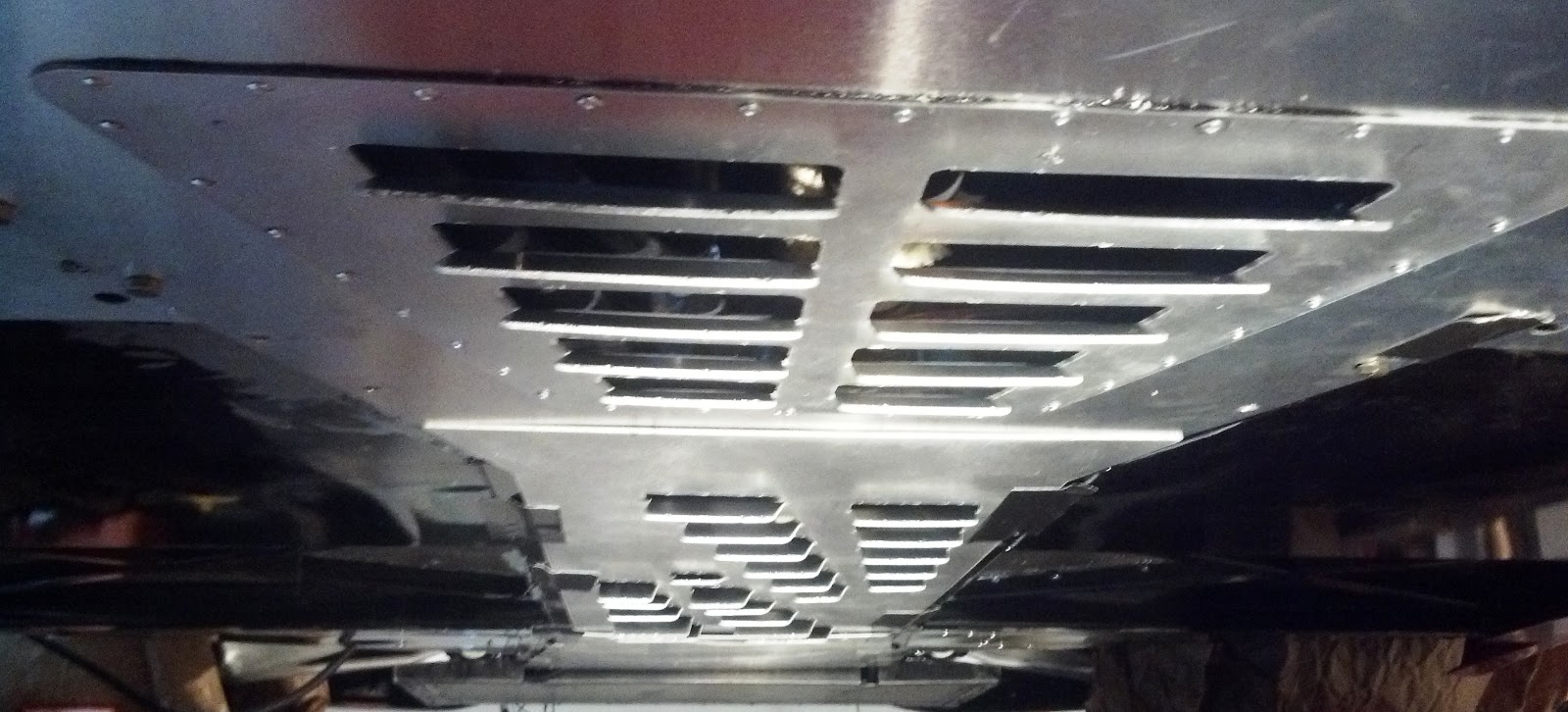
This is the Vraptor vented piece that replaces the triangular access panel. This is shipped flat. I found the knife (to the right) turned out to be the best tool to open up the vents.
Basic kit piece with access panel cut.
Rear piece with vented access panel riveted into place. (Yes, this is a design change.)
The Helicoil procedure (this is for 1/4 - 20 inserts) is as follows:
  1. Drill a pilot hole using a 1/8 inch bit. (This isn't always necessary, but I did this to guide the drill when making the main hole.)
  2. Drill a 17/64 inch hole.
  3. Use the Helicoil supplied tap bit. (This is a proprietary bit size - the only thing I don't like about this product.)
  4. Thread the insert on the thread bit. It will come a stop when it meets the tang. 
  5. Apply thread lock (either blue or red) to the insert.
  6. Slowly screw the insert into place, and give it time (overnight) to set up.
Drilling 70 plus holes into the bottom of the chassis frame is not an easy task. I raised the lift high enough to get my head under the car, then used a right handed drill and used my entire body (starting with the knees) to drill upwards. Yes, I was sore and I got tired. The result is that all undercarriage aluminum panels running from the radiator box to the engine bay are removable (same as my Porsche Boxster).
These are the Vraptor pieces ready for install on the car.
This is the front piece (left) and the central tunnel piece (right).
 I used the kit supplied triangular plate as a template for the holes. I taped the Vraptor panel between the larger piece and the access piece, then drilled through the solid access piece. Once I had everything drilled, I went ahead and riveted the two pieces together.
Orientation: Engine bay facing forward under the car.
Orientation: Driver's side from rear wheel.
Out of the 70 plus Helicoils installed on the underside of the chassis, I think I have two that are messed up. I will just redrill and tap a new insert into place.

Sunday, November 4, 2012

Gen II GTM Front Grille


 << Mount DRLs                                                 Forward Parking Assist - Circuit 3/9 >>

Major System Category: Body (Hood)
Task: Install front grille
Parts: Vraptor Gen II Grille
Prerequisite Tasks: fender louvers
Additional Costs: $78
Time Requirement: 3 hours
Date Started: October, 10, 2012
Date Completed: October, 12, 2012
The GTM has to have a grille. This is a sports car with great lines. I don't remember if the Gen II has a screen mesh or just leaves things open. Either way, it is kind of ugly. After all, who wants to look into the front of a car and see the radiator? The grille adds cost to the kit and mesh is a cheap alternative. This is not a criticism, just a fact. A builder on a budget can go either way.
The grill come with three brackets. The center is a bit bigger than the sides. The end with the hole in it is the  top of the bracket.


The brackets need to be bent a certain way. I used a vice to make the bends.
The front grille is another Vraptor design. This is a totally optional part. The car will function without this addition. However  anyone building a GTM is going to consider using some of what Vraptor has to offer. On top of that Shane is a great guy. He posts frequently on the forums. He will answer questions via email. Stuff always shows up fast. I think I am on order #4 right now.
This is the grille prior to installation. She is painted and bonded at this point.
One thing mentioned in the instructions is that the front end opening (where the grille is mounted) is not centered on the hood. It is off by about 1 inch (sigh). Basically the instructions advise that you can center the grille to the car and look weird, or you can center the grille inside the opening and look okay. (Again, I do not understand why the hood is so off.)
This is the grill opening with the three brackets in place. I was just getting a sense for where they needed to go.  Clearly visible is the radiator, AC condenser and fan assembly (yuck!). 
This is the grille centered inside the opening. Once I started working on the front end of the hood, I just kept going.  October was basically spent working on the hood.
 The grille mounts on the inside lips that form the opening. The test mount was with the parts unpainted and held together with Gorilla Tape. I raised the lift to chest level and went to work. I think I even ran the laser level to see the center of the hood versus the center of the grille opening. Once I was satisfied that everything was going to be okay. I used 3M 8115 panel bond to permanently bond the grille and painted it gloss black.

A different angle.

Fuel tank to fuel filter to fuel pump


<< Install Cross Over Tube                     Tunnel Floor and Venting >>

Major System Category: Fuel System
Task: Install fuel filters and fuel pump
Parts: Fuel pump and plumbing
Prerequisite Tasks: Aluminum Tanks
Additional Costs: $930 (entire fuel pump and fittings)
Time Requirement: 3 hours (plus some staring at stuff time)
Date Started: November 3, 2012
Date Completed: November 3, 2012
The is the box of parts from QRP. There are instructions included for how to wire up the fuel bump and filters and regulator. It is up to the builder to figure out the best way to plumb the fuel lines. Once you sit down and think it, this isn't that hard to do.
Note: This post does not reflect the Factory Five build manual. I am using QRP's aluminum tanks and external fuel system. This is a personal choice that reflects my belief that this is a better way to go.
Holley fuel pump with the anti vibration mounts attached.
To say that the box of parts for the fuel system is a little intimidating is something of an understatement. The first thing I did was separate everything into their like parts. There 6 AN and 8 AN fittings. There is steel braided hose for 16 AN, 8AN and 6 AN. There are elbows, straight couplers, hose fittings, a pre and post fuel filter, pressure regulator, gauge and the fuel pump.
This is the supply line from the driver's side fuel tank to the fuel system. This is a 8AN fitting.
Consideration: This is definitely a task that should be done BEFORE  the engine is put into the car. You can stand in the engine bay and work on this stuff. Also connect the cross over tube FIRST. This sets the tanks in place.

Fundamentally, this is what has to happen:
  1. Run a 8 AN line from the driver's side fuel tank to a pre fuel filter. This is the small one.
  2. Connect the pre fuel filter to the fuel pump using 8AN fittings.
  3. Connect the fuel pump to the the post fuel filter using 8 AN fittings. This is where I used the nifty 160 degree elbow fitting to navigate the sharp angle above the fuel tank housing.
  4. Exit the post fuel filter with a 6 AN fitting. Since everything else is a 6 AN fitting in the kit, I am guessing the connection to the fuel rails are 6 AN.
Supply line from the fuel pump connected to the pre fuel filter. This is going to be  routed into the fuel pump, but I need a 8AN/8AN straight coupler to make that happen.

Fuel pump and post fuel filter mounted and the panel above the fuel tank on driver's side.  
This required me to make the following lines:
  1. 8AN line from the fuel tank to the pre fuel filter. This approximately 16 inches long.
  2. 8AN line from the 160 elbow to the post fuel filter. This about 6 inches long.
This is the supply line from the fuel tank to the pre fuel filter.

This is the supply line from the fuel pimp to the fuel filter. See the nifty 160 degree elbow.
I have a video on how to build the AN lines on my cross over tank post.

Consideration: When measuring steel lines, the tape measure is great for an initial idea. However, I found that the steel lines do not bend sharply, so it was best to run the line along the same route and mark the line where it comfortable terminates.

Thursday, November 1, 2012

Fuel Tank Crossover Tube


<< Install Fuel Tanks                      Driver's Side fuel pump >>

Major System Category: Fuel System
Task: Install Cross Over Tube
Parts: Fuel pump and plumbing
Prerequisite Tasks: Aluminum Tanks
Additional Costs: $930 (entire fuel pump and fittings)
Time Requirement: 90 minute
Date Started: November 1, 2012
Date Completed: November 1, 2012
I received the QRP fuel pump system the week before we went to San Diego. So it has been sitting in my office for about two weeks. This is a box full of fittings, braided hoses, a relay, pressure gauge, fuel filters, anti vibration mounts and the Holley fuel pump. At first blush, this is a head scratcher.
This is the box of goodies QRP supplies for the fuel pump side of the  fuel system.

The first thing I needed to figure out was how to attach a AN fitting to a braided steel hose. A quick Google search found a great little YouTube video that even a computer geek can follow. I knew I was in the right place, because it featured a big hammer.

The easiest thing to do in the fuel system is to run the cross over tube between the two tanks. This is a really big steel braided hose with AN 16 fittings on each end. It is better to start out with a finished piece that is too long instead of too short. The secret to making this work is tilting one of the tanks so the tank's AN fitting is outside of the cut out in the tunnel. This enables the cross over tube to fit between the tanks. As you screw things in, everything comes back into place.
This is the piece as delivered by QRP. These guys are very generous. They provide enough hose to make 2 crossover tubes (just in case you screw it up the first time.) 

This is my finished hose. 

I had to go back twice to trim an inch off the tube. I wanted to make sure there was some slack in the line, but this is a relative concept. If there is too much slack it is not possible to connect the tanks, and it there is no slack, you have to start over.
Installed inside the tunnel between the two fuel tanks. This is about 12 inches further into the tunnel than when the Corvette donor tanks are used. This means it is further away from the heat and moving parts.

Saturday, October 6, 2012

Side Scoop Louvers


<< Shaved handles                                        Rear Brake Vent >>

Major System Category: Body (Shell)
Task: Prep and install side scoop louvers
Parts:
Prerequisite Tasks: Mount the body
Additional Costs: $126
Time Requirement: 5 hours
Date Started: September 16, 2012
Date Completed: September 25, 2012
The side scoops are located forward of the rear tires. The build manual calls for a mesh screen to be installed  behind the cut out. There is nothing wrong with mesh screen, it just doesn't provide for enough air flow. I believe this was done as a cost control measure. The basic kit already costs $21k plus shipping and the donor and the transaxle. All told, the basic car costs around $55k. This is a no frills, basic GTM. Engineered parts like louvers cost more and further complicate the build. There is a trade off here.
These are the different parts and pieces for 1 side scoop louver. Basically, there are two side pieces and  eight blades.
I made the decision to spend dollars to enhance the car's integrity. Items such as the roof scoop (a F5 option in the catalog), bump/steer kit, Z06 Big Brakes, larger wheels, aluminum tanks and so forth are optional. The same goes for louvers. I purchase the side scoop louvers to replace the mesh screen.
One side louver assembled. This looks like the passenger side louver.
Consideration: I definitely would want to do this before installing the fuel tanks. This is a room to work consideration.
These are louvers side by side. They are not bonded at this point and can fall apart  in your  hands.
Each louver consists of 10 pieces. To figure how to put these together, I examined the photos on the Vraptor Speedworks site and measured the install area for the scoop. The photos showed eight louvers (same as in the kit). I discovered from my measurements that the cut out is not single width from top to bottom. This helped me understand that the widest louvers need to me i the middle, followed by the slightly shorter width louvers and a top and bottom piece. The top and bottom become obvious when examining the depth of cuts on the side pieces.
This is a test fit of the louver on the driver's side. It is just sitting in there.
I assembled a left and right version of the louvers (I got it wrong a couple of times). The skinny side piece goes against the interior of the other shell and the fatter side piece encloses the inside of the scoop. (This becomes obvious when you get under the car and look.
These are the louvers bonded and painted. I ended up having to  sand and repaint parts of the louvers after they were installed. There was a certain amount of fiber glass and glazing necessary to sculpt the opening.
Consideration: I used tape on the outside of the side pieces to hold everything together. This facilitates a test fit and measurement for the cut out. I intend to use 3M 8115 panel bond to permanently secure these pieces.
Final product. The louver is bonded to the body shell. The opening has been sculpted with  fiber glass, sanded and glazed. I am sure it will need some additional attention before it is ready for paint, but that's a long way off right now.

It helps to remove the tires in order to provide access inside the body shell (thank goodness for the inline jacks). The scoop cut is basic grunt work.
Search Engine Submission - AddMe