Showing posts with label body shell. Show all posts

Friday, January 9, 2015

Racing Wing (optional component)

<< Weld Wing Mount to Transaxle Bracket                          >>

Major System Category: Brakes & Suspension
Task: Mount Racing WIng
Parts: Wing Mounts
             Racing Wing
Prerequisite Tasks:
Weld Wing Mount to Transaxle Bracket
Additional Costs:
Vraptor Speedworks Universal Wing Mount $489
APR GTC-300 Carbon Fiber Wing $1350
Time Requirement: 4 hours
Date Started: January 6, 2015
Date Completed:  January 8, 2015
I told my long time sparring buddy that I was getting ready to cut into the back end of the car. He expressed concern. I explained that after this much time on the car, very little frightens me anymore. Besides fiber glass can be fixed.
The wing arrives in a long box and wrapped in bubble wrap.

To give a sense of scale, the rolling bench is 48 inches long. The wing is 67 inches.
 All parts are purchased from Vraptor Speedworks (Shane does a great job). The Vraptor wing is the same one offered through the Factory Five website. The main difference is the attachment points are custom to the Vraptor mounting system. This is a very solid piece of gear. The back end is greatly reinforced by this addition.
The initial cut. I originally figured it would be 7 1/2 inches long. I needed 8 inches to make everything work.
I added rear body shell louvers to the build. I masked off the area, and came up with a rough measurement of 2 7/8 inches from the edge of rear louver opening. The mount comes in three parts that are bolted tot he welded transaxle bracket, then bolted side ways through slots for the portion that pokes through the rear body shell, and finally the third piece that rests above the body shell. All that to say I was inside of a 1/4 inch and well within tolerances for the mount adjustments.
The cut needs to be this wide to work. I already have a solution for cleaning up the edges.
I used a angle grinder to make the initial cuts. Once those were wide enough, I used a rigid sanding wheel on a die grinder to shape, smooth and widen the cut. I strongly recommend wearing a breathing mask and face shield. There is a great deal of dust released when cutting into the back end like this.
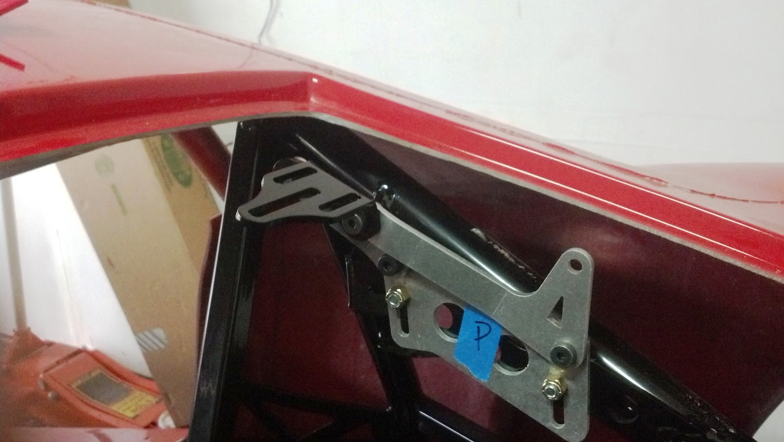
This is the middle part of the bracket poking through the hole. This is secured to the bottom bracket by three bolts.

The cut ended up being 8 inches long. I ended up about 1/2 inch off the rear of the car, and I had to trim some material around the exhaust vent openings. Keep the socket wrench and hammer handy, because I had to loosen the bottom of the bracket and tap it back and forth to line things up.
This shows the middle and top part of the mount bolted together and the length of the cut.
The second cut went much faster (probably, because I had some idea of what I was doing).This was on the passenger side, and this is where I need to move it over a tad. I don't think the difference will be noticeable.
Driver's side mount installed. Once I got to this point, I knew I'd get to the end of this task tonight.
Once I had the middle and bottom brackets bolted together, it gets very easy. The one thing I ran into was the bolt closest to the rear of the car is snug. Not uncomfortably snug, but I had to use hand tools and not my power tools to tighten it up.
Both mounts in place. I have a card board covering for the rear louver.
The rest is very straight forward. I was really excited to see the wing on the mounts on the car. Granted it is just resting on the mounts, but that's not a big deal.
Yes!

Wednesday, November 20, 2013

Weld Wing Mount to Transaxle Bracket

<<  Mount Rear Suspension                                                 Transaxle Delivery >>
                                                                                               Racing Wing >>

Major System Category: Transmission
Task: Weld Wing Mount to Transaxle Bracket
Parts: Vraptor Wing Mount
Prerequisite Tasks: 
Additional Costs: $500 parts, $100 welding
Time Requirement: 1 Hour
Date Started: August 15, 2013
Date Completed: August 15, 2013
One of the optional items for the car is a functional wing. The wing advertised on the Factory Five site is the APR-300 67 inch wing made out of carbon fiber. The photos on the parts catalog page indicate the racing wing attaches  to the rear deck of the body shell. While the rear deck is reinforced by the transaxle bracket it is still fiberglass and it is not a direct connection to the frame. I a, mot sold on the idea that the fiber glass body shell can handle the stresses that are generated by a functional wing.
This is the universal wing mount kit from Vraptor. Four of the pieces are welded to the transaxle bracket. The other two pieces are bolted to the welded pieces and extend through the body shell to mount the APR wing.
This is where Vraptor Speedworks comes to play. They sell a universal wing mount that is welded to the transaxle bracket. A competent welding shop can weld these pieces for about $100 - in my case Crystal Welding. A wing mount that translates down force to the frame rather than the body shell. This thing is solid like a rock. This can handle whatever stresses I generated with a LS76/525 engine mated to a 7 speed transaxle on Nitti INVO tires. 
Top view of the modified transaxle bracket,
The transaxle bracket is secured to the chassis using four bolts. One of the things that concerned me was there going to be enough clearance when the transaxle is sitting in the cradle. Once the transaxle arrived, I discovered I had to further modify the transaxle bracket to handle the sleeve where trhe transaxle bolts to the bracket. I'm pretty sure there is no problem with the bolts. It turns out the Porsche 991 transaxle needs 3.5 inch sleeve, and the bracket I have only goes to 3.75 inches.
Bottom view of the modified transaxle bracket.

Sunday, August 25, 2013

Exhaust Vent

<< Rear Body Louvers                              Shaved Handles >>

Major System Category: Body (Shell)
Task: Cut the two openings for the exhaust.
Parts:
Prerequisite Tasks:
Additional Costs:
Time Requirement: 1 hour
Date Started: August 22, 2013
Date Completed:  August 22, 2013
I had not planned on cutting the exhaust vents at this point in time. However, I went through my collection of scrap fiber glass (basically, pieces that have been trimmed from the car already), and discovered I didn't have a piece large enough to cut plates for the shaved door handles. It didn't occur to me right away, but the exhaust vents offer a large enough piece for the door handle plates.
Even though I flubbed drawing the line, I did cut it straight.
This is a very straight forward task (that requires a modicum of ingenuity to get done). If you think that's a contradiction, then you haven't been building a GTM for the past year. The build manual instructs to measure 8.5 inches from either side of the center indentation where the license plate is mounted. Note: The indentation is slightly trapezoid  so measurements need to account for a slight difference top to bottom.
Here are the cut out pieces for the exhaust vents. Now I can form the plates for the shaved door handles.
I used a Dremel tool and a die grinder with cut off wheels to make the initial cuts. My preference is the Dremel tool, because it is easier to be precise. There some difficulty in getting the small Dremel cut off wheel inside the indentation to get all the way through the fiber glass. Once I had some initial cuts made, I was able to enlarge from the inside portion of the body shell. I had to be careful so I didn't get a cut going at an angle. Next, I took a reciprocating saw to finish the cuts, then a sanding block to smooth out the cut edges.
Old license plate just to see how it would look. 

Tuesday, July 9, 2013

Seam Glassing

<< Fender Louvers                                                       Hood Preparation >>

Major System Category: Body (Hood/Shell)
Task: Smooth out seams on fiberglass shell
Parts: Bondo, fiberglass
Prerequisite Tasks:
Additional Costs: $30
Time Requirement: 40 -50 hours
Date Started: June  20, 2013
Date Completed:  July 9, 2013
When the body arrives on the truck, it appears to be a single body. Reality is much different. There are five main body parts:
  • Hood,
  • Rear body shell,
  • Left and right doors
  • Hatch
Main hood seam. I have the fiber glass cloth just taped in place.
The hood and body shell are delivered as single pieces, but part of the manufacture process involves bonding   different parts together. There is a seam along these joints where the bonding compound has been squeezed and forms an uneven ridge. Also the mated pieces are uneven (i.e. the mated pieces are higher or lower than the other side).
Driver's side seam  that has been sanded down. The fiber glass strip is gut and sitting above the seam.
The hood seams run over the top of the wheel wells, down to the grill and across the front. If your build includes fender louvers, then handle those first. The fender louvers will cover a good chunk of the top seam over the wheel wells. Some people choose to rivet the fender louvers in place, I used 3M's 8115 panel bond to attached the louvers. Then I feathered the ridge created by the louvers to blend into the hood (this is a lot more work).
Passenger side A pillar seam. This looks pretty rough here. I haven't sanded anything, just have the bondo and fiber glass applied.
The seams are uneven ridges along the body. If you are working with a GTM or some other Factory Five model you will notice these ridges. This is part of the body work necessary to complete the car. Most guys that can afford to build a GTM farm this out, but some of us either decide not to or don't have the money to spare. Fiber glassing the seam basically hides and smooths out these areas It isn't that hard to do and after a while you might even get good at it.
Major amount of work. The front hood seam is fully sanded. The entire hood has been sanded once using the orbital sander and secondly using the Dura Block kit. The hood louvers are easy as they are bonded from inside the hood. The fender louvers are a major time investment.
Recommended tools:

  1. Orbital sander
  2. Dura-Block sanding kit
  3. Bondo and fiberglass material.
  4. Spreaders.
  5. Glazing compound.
  6. I didn't think these were as good as they are. If you plan to work on the body and sanding yourself, then this is a must must buy!
The first thing you need to do is even out the ridge. Some of these ridges are hard and brittle, others can be a little soft. You can use a hand block or a mechanical tool, you just want to be careful about gouging the hood and body shell. Any gouges will need to be repaired. You won't be able to totally eliminate the ridge, because most likely the two pieces that were bonded are an uneven join. Just do the best you can. When you finish no one will see them anyway.
This is the seam that runs the length of the body shell. This is on  the passenger side. This car also has a roof scoop, so you can see some of that work running parallel to the body seam.
Cut a strip of fiber glass cloth for the seam you plan to work on. I would start out short and between 3/4 to 1 inch wide.
This is the passenger side rear quarter panel. The seam runs down and under the car. It is one of those awkward spots to work. It also a little loose, because I have the transaxle bracket currently removed from the frame. This bracket provides much needed bracing to the rear body shell.
Mix up some bondo (this stuff can harden up pretty fast, so get ready). For this I sometimes wore a disposable plastic glove and/or a spreader. I found my finger worked pretty well for some areas where it was awkward to use a spreader. I applied the bondo, evened it out as much as possible then, layered the fiber glass strip over it.
Rear quarter panel on the passenger side. It has bondo and fiberglass applied and still requires sanding in this photo. The body work takes a long long time to do.
I let this set up. Usually, 45 to 60 minutes, then I apply a second layer of bondo over the fiber glass strip.
This is the hardest set of seams to work on. They are curved and in a very enclosed area. This is the big brake vent just behind the drivers side door. I saved this for last.
Once this is hardened up, I go to work with the sanding tools. I use the orbital sander to get rid of the excess, then go to work with a block sander by hand. I work on it until it is fairly smooth. I am using 220 grit, although, I understand you can get away with 180 grit.
To get an idea of the success/failure of my body efforts, I test primed the front seam. For the most part this worked. I still have issues around the fender louvers and the area where the seam goes over the front flare. However, this was a big boost to my efforts, because it showed me that I could get the car to a point where the seams are smooth enough for paint. 
I keep working the seam until I'm satisfied. This gets to be pretty messy.
I ordered 2 kinds of primer for my seam test. I only applied the rapid primer filler. The other one is an epoxy primer that I will test once I am happy with the seams. I got these at 66 Auto color. This is pretty caustic stuff, so you need a rudimentary paint booth or real good ventilation and a respirator.
I wipe down everything using a microfiber cloth and water to remove the main layer of dust. Then I inspect for deep gouges or holes, and use the glazing compound to sculpt in fixes. I keep going over this until I'm satisfied. I keep working it until it is smooth to the finger test.
The fender louvers continue to cause me issues, but I am confident I came make these blend into the car.
The body work can be pretty intimidating, but wow, a little success can be a real confidence builder. I now see nothing that can prevent me from completing this project.

Sunday, November 4, 2012

Gen II GTM Front Grille


 << Mount DRLs                                                 Forward Parking Assist - Circuit 3/9 >>

Major System Category: Body (Hood)
Task: Install front grille
Parts: Vraptor Gen II Grille
Prerequisite Tasks: fender louvers
Additional Costs: $78
Time Requirement: 3 hours
Date Started: October, 10, 2012
Date Completed: October, 12, 2012
The GTM has to have a grille. This is a sports car with great lines. I don't remember if the Gen II has a screen mesh or just leaves things open. Either way, it is kind of ugly. After all, who wants to look into the front of a car and see the radiator? The grille adds cost to the kit and mesh is a cheap alternative. This is not a criticism, just a fact. A builder on a budget can go either way.
The grill come with three brackets. The center is a bit bigger than the sides. The end with the hole in it is the  top of the bracket.


The brackets need to be bent a certain way. I used a vice to make the bends.
The front grille is another Vraptor design. This is a totally optional part. The car will function without this addition. However  anyone building a GTM is going to consider using some of what Vraptor has to offer. On top of that Shane is a great guy. He posts frequently on the forums. He will answer questions via email. Stuff always shows up fast. I think I am on order #4 right now.
This is the grille prior to installation. She is painted and bonded at this point.
One thing mentioned in the instructions is that the front end opening (where the grille is mounted) is not centered on the hood. It is off by about 1 inch (sigh). Basically the instructions advise that you can center the grille to the car and look weird, or you can center the grille inside the opening and look okay. (Again, I do not understand why the hood is so off.)
This is the grill opening with the three brackets in place. I was just getting a sense for where they needed to go.  Clearly visible is the radiator, AC condenser and fan assembly (yuck!). 
This is the grille centered inside the opening. Once I started working on the front end of the hood, I just kept going.  October was basically spent working on the hood.
 The grille mounts on the inside lips that form the opening. The test mount was with the parts unpainted and held together with Gorilla Tape. I raised the lift to chest level and went to work. I think I even ran the laser level to see the center of the hood versus the center of the grille opening. Once I was satisfied that everything was going to be okay. I used 3M 8115 panel bond to permanently bond the grille and painted it gloss black.

A different angle.

Wednesday, October 3, 2012

Hood Latches


<< Gas struts                                                         Mount Fog Lights >>

Major System Category: Body (Hood)
Task: Install latches and strikers
Parts: Corvette donor latches/strikers
Prerequisite Tasks: gas struts
Additional Costs: $20 Hood latch rub plates
Time Requirement: 90 minutes
Date Started: September 30, 2012
Date Completed: October 1, 2012
The latch and striker system use Corvette donor parts. There is a driver and passenger side version of the latch. The rule of thumb is that the side with the two square cut outs face front. In my case, the Corvette latch bolts were available. I used those with an extra set of washers on the inside of the body shell.
The side of the body is marked up for the latch install. The Corvette donor bolts are  1/4 inch,  so I drilled the center of the square cuts to give me some latitude to adjust the latch position on the body. Orientation: Driver side latch.
Consideration: It is much easier to do when the doors are uninstalled. The back of the latch can be reached from both the wheel well and door opening.
Corvette donor latch installed, with the Vraptor Speedworks rub plate between the latch and the body shell. I painted my rub plates black. They come unpainted. The square cut outs on the rub plates match the donor hardware.  Orientation: Driver side latch.
I purchased the Vraptor rub plates. These were originally called paint savers. Basically they act as a shield between the striker and the fiber glass behind the hood latch.
This the edge where the hood mates to the body shell. My goal is to keep this aligned. My other goal is to  keep the  left/right and up/down measurements for the hood with 1/8 inch tolerance. These goals do not play nice together.  Orientation: Driver side latch.

Consideration: The manual has this paint marking scheme to figure out the position of the striker. While this might work, it ignores the alignment of the hood and body lines. I developed a different methodology for striker placement.
My method measures from the edge of the body shell to the center line of the latch where the striker  mates. This approximately 9 inches.
My methodology is as follows:
  1. Close the hood and ensure the edge of the hood aligns to the edge of the body where they meet towards to top of the door opening.
  2. Position the hood latch so it sits in the middle of the up/down and forward/backward. This is so it can be adjusted.
  3. On the body, run a measurement from the edge to the center line of the latch. I found this to be approximately 9 inches.
  4. Run the same measurement on the hood and project a line perpendicular to the mounting block for the striker. This line aligns to the striker.
  5. Duct tape the striker in place and bring it down to the latch. It isn't very easy to see the striker and the latch, but I was able to reach my finger up and feel the location of the striker, then I just lifted the hood to verify the location.
  6. Adjust the latch/striker as necessary.
  7. Tighten everything down and test latch the hood.
I make a similar measurement with the hood. This one is harder to do because the body shape curves and the mounting block for the sriker is about 2 or 3 inches away from the edge.
The hood is going to want to creep around in terms of fitment. Right now, I am fairly happy with how it turned out. I reran the laser level against the hood. She is still within 1/8 of inch left to right.

Thursday, September 27, 2012

Door Panels (Sound Proof)


<< Mount the Body Shell                                                             Preliminary Fit >>

Major System Category: Sound/Heat Proofing
Task: Apply sound proofing materials
Parts:
Prerequisite Tasks: Need to be finished with an area
Additional Costs: $100
Time Requirement: On going
Date Started: September 10, 2012
Date Completed: September 10, 2012
My plan was to work my way around the car. The next item I planned to tackle was the passenger side door. There's just one glitch in this plan. I am still waiting on the front door trim panels. I need these pieces to anchor the internal door frame.
Sound proofing the interior door area.

I had retrieved the doors from my storage locker (about 4 miles down the road). It was sometime after I had everything else set up to start working on the doors that i realized I did not have this piece of the puzzle. There are other pieces I could have worked around, but I did not want to guess about placement for things with the front trim panels.

I decided to sound proof the inside of the doors. This was the one thing I could get done. This is a easy task to accomplish. I kept the area around the door handle free (for the moment), just in case I change my mind about the door poppers, or if they prove unreliable. However, my intention is to close them off and cover them with a spare piece of fiber glass.

Note: Initially, I was concerned about miscellaneous fiber glass pieces, but once I started on the body cut outs for the body shell, I realized I had enough for the shaved door handles.

Tuesday, September 25, 2012

Rear Brake Vent


<< Mount Body Shell                                        Next Link >>

Major System Category: Body (Shell)
Task: Cut out rear vent slots
Parts:
Prerequisite Tasks: Mount the body
Additional Costs: N/A
Time Requirement: 2.5 hours
Date Started: September 17, 2012
Date Completed: September 21, 2012
I seemed to have more trouble cutting out these little slots than all the other body cut outs I have performed. Anyway, when I finished they were jagged and rough. I used a file, the Dremel with a drum sander and 180 grit sand paper to get things evened out. This is the only area that I plan to use the Factory Five supplied mesh.
Rear vent screens after they are formed and painted.
I painted the mesh screen black. This is keeping with the gloss black accents I am incorporating into the car's image. Next I did a test fit of the screen against the opening. The screen needs to be formed to the contour of the inside of the rear vent. To bend the mesh, I used a vice to evenly bend the creases at something less than a 90 degree angle. This is keeping with the angle of the fiber glass form on the inside of the body shell. There's no need to be exact. You just need the creases to work with.
3M adhesive tape applied to the screen mesh. Ready for install.
I used 3M double sided adhesive tape to attach the mesh to the side of the fiber glass. I have used this successfully on my Corvette in attaching Race Mesh grills to the brake ducts. I applied the 3M tape in two strips. Be careful not to roll the tape when applying the mesh screens to the fiber glass.
Final install.
The final bit of work requires sanding and glazing putty to smooth out the cuts. I work these tasks in around other things I am doing on the car. They take time, but in small chunks, as I have to wait for things to dry.

Wednesday, September 12, 2012

Rear Hatch Latch


<< Rear Hatch Gas Struts                               Rear Hatch Release Popper >>

Major System Category: Body (Hatch)
Task: Install latch
Parts: Latch parts
Prerequisite Tasks: Assemble and mount hatch latch
Additional Costs:
Time Requirement: 2 hours
Date Started: September 12, 2012
Date Completed:  September 12, 2012
The actual work on the hatch is fairly straight forward, but it took me 2 days to figure what the procedure was telling me to do. Once I figured out the orientation and understood that one of the parts was reversed from the mechanical drawing, things fell into place.
Striker and striker plate with the washers inserted for temporary assembly. I probably could have tightened this down for real, but I was just being slow and cautious.
Consideration: There is very little room for error when assembling this piece. So measure twice, then measure again. Take your time.
These are the rivet inserts located on the inside of the hatch. Factory Five has done a good job in creating  mounting  plates for rivets and rivet inserts.
The first thing I did was assemble the striker with a pair of washers. This was so I did not tighten down everything into the nylon locking nut. This allowed me to have the striker assembled to the correct length. I taped and clamped this to the hatch. I clamped the latch to the body shell tab.
These are the holes drilled for the latch into the tab that hangs down from the body shell. You can see my scribbles with the Sharpie. Orientation: looking towards the rear from inside the engine bay.
The manual says to measure 15/16" from the body shell to figure out where to mount the striker. In a perfect world, this might work. In my world, this isn't quite far enough. I eyeballed the striker plate (minus the striker) and the latch. When everything lined up, I marked those locations with a Sharpie. I then put the striker on the striker plate. This caused me to back off the striker plate from the body shell so the end of striker slides between the latch and the body shell.
This is the big hunk of metal that acts as brace for the  latch. These holes are for the  same rivet inserts drilled for the latch in the previous photo. This is Factory Five's solution to reinforce the tab for the body shell where the latch is attached. I think this area may require additional reinforcement.
I marked the locations for the rivet inserts. I drilled pilot holes with 1/8" bit, then drilled the final holes with the 25/64" bit. I attached the striker first. My thinking is there is more wiggle room for the latch (i.e. it can be adjusted prior to final install to match up with the striker). Once I was satisfied, I drilled out the holes for the second set of rivet inserts. Insert screws and tighten everything down. It is either going to work or fail. The final test was seeing if it works and it did - wow!
This the is hatch latch and striker closed. I plan to get a shaved door handle kit that includes a  trunk popper. I may have to fabricate some sort of brace for the popper solenoid, but it seems much more reliable than running a really long cable into the cockpit.

Wednesday, September 5, 2012

Rear Hatch Hinge


<< Rear Hatch Fitment                                        Hatch Gas Struts >>

Major System Category: Body (Hatch)
Task: Assemble and mount the hinges
Parts: Hatch hinges
Prerequisite Tasks: Preliminary hatch fitment
Additional Costs:
Time Requirement: 90 minutes
Date Started: September 1, 2012
Date Completed:  September 1 , 2012
The hinges are straight forward. The photos in the build manual give a basic understanding of how these fit together. There is a specific right and left hinge configuration. Basically, the hinge needs to move so it does not bind.
Hinge pieces. The manual photos can get you turned around, so just  use common sense when fitting the bushings.
Factory Five did a good job in designing adjustments for the hinges. They can move up, down, forward and back. Like most builders, I found the hatch to be high on one side and lower on the other. This is not something that can be forced into place. In order for the hinges to function properly, they need to rest flush against the top inside section of the hatch.
Hinges assembled. I marked then P(assenger) and D(river). It  got a little muddled when I stood in the engine bay.
Unfortunately, when the hinges line up with the mounting pads on the hatch, the preliminary fitment tends to shift in some direction. I used a Sharpie and marked the lines inside the hinge groves where the hinge plate mated to the hatch. I then drilled and install the rivet inserts. The hatch is molded around a soft piece of aluminum, and there is a space under the aluminum, so be careful when you drill.
Passenger side hinge closed after initial attachment to the chassis.
I spent a fair amount of time working with the hinges and the hatch fitment. Finally, I loosened up everything connected to the chassis, and let the hinge/hatch move into place. This changed my preliminary fitment, but the hatch relaxed into the body shell. I have some high spots, but I plan to use Bondo to even out the fitment issues.
Hinge open on the passenger side.

Search Engine Submission - AddMe